OPERATING TEMPERATURE
(Command: .TEMP) in degrees Celsius °C.
The operating temperature of an analysis can be set to any desired value by the .TEMP command .The general form is,
.TEMP { (one or more temperature) values } [default 27 °C]
Some temperature statements
.TEMP 50
.TEMP 25 50
.TEMP 0 25 50 100

Custom Search
Thursday, July 17, 2008

Wednesday, July 16, 2008
Program for analysis of three phase circuit representing generator transmission line and load - PSPICE
The aim of the program is to analyze the three phase circuit representing generator transmission line and load and to plot 3 phase current and neutral current.
Problem:
220v, 50hz supply is applied to
a) balanced 3-phase star connected load contains 25 ohms of resistance and 6mH of inductance in each phase
b)
Un-balanced 3-phase star connected load of 10 ohms, 3mH inductance, 20ohms, 4mh & 30 ohms , 5mh inductance for 3-phase respectively. Plot 3 phase currents and neutral laod. If source L is 6mH and value of neutral inductance is 7mH
PROGRAM CODE ( for balanced 3-phase analysis )
*balanced 3-phase analysis
*source description
VS1 1 2 SIN(0 220 50HZ 0 0 0DEG)
VS2 1 4 SIN(0 220 50HZ 0 0 120DEG)
VS3 1 6 SIN(0 220 50HZ 0 0 240DEG)
VS4 10 9 DC 0V
VS5 10 11 DC 0V
VS6 10 13 DC 0V
VS7 0 10 DC 0V
*COMPONENT DESCRIPTION
L1 2 3 6M
L2 4 5 6M
L3 6 7 6M
L4 1 0 6M
L5 8 3 6M
L6 14 5 6M
L7 12 7 6M
R1 8 9 25
R2 12 11 25
R3 14 13 25
* ANALYSIS DESCRIPTION
.TRAN 20ms 160ms
*OUTPUT DESCRIPTION
.PROBE
.END
OUTPUT

PROGRAM CODE ( for Un-balanced 3-phase analysis )
*unbalanced 3-phase analysis
*source description
VS1 1 2 SIN(0 220 50HZ 0 0 0DEG)
VS2 1 4 SIN(0 220 50HZ 0 0 120DEG)
VS3 1 6 SIN(0 220 50HZ 0 0 240DEG)
VS4 10 9 DC 0V
VS5 10 11 DC 0V
VS6 10 13 DC 0V
VS7 0 10 DC 0V
*COMPONENT DESCRIPTION
L1 2 3 6M
L2 4 5 6M
L3 6 7 6M
L4 1 0 6M
L5 8 3 3M
L6 14 5 4M
L7 12 7 5M
R1 8 9 10
R2 12 11 30
R3 14 13 20
* ANALYSIS DESCRIPTION
.TRAN 20ms 160ms
*OUTPUT DESCRIPTION
.PROBE
.END
OUTPUT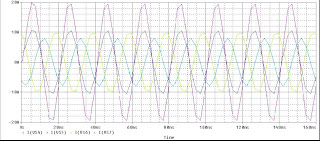
Problem:
220v, 50hz supply is applied to
a) balanced 3-phase star connected load contains 25 ohms of resistance and 6mH of inductance in each phase
b)
Un-balanced 3-phase star connected load of 10 ohms, 3mH inductance, 20ohms, 4mh & 30 ohms , 5mh inductance for 3-phase respectively. Plot 3 phase currents and neutral laod. If source L is 6mH and value of neutral inductance is 7mH
PROGRAM CODE ( for balanced 3-phase analysis )
*balanced 3-phase analysis
*source description
VS1 1 2 SIN(0 220 50HZ 0 0 0DEG)
VS2 1 4 SIN(0 220 50HZ 0 0 120DEG)
VS3 1 6 SIN(0 220 50HZ 0 0 240DEG)
VS4 10 9 DC 0V
VS5 10 11 DC 0V
VS6 10 13 DC 0V
VS7 0 10 DC 0V
*COMPONENT DESCRIPTION
L1 2 3 6M
L2 4 5 6M
L3 6 7 6M
L4 1 0 6M
L5 8 3 6M
L6 14 5 6M
L7 12 7 6M
R1 8 9 25
R2 12 11 25
R3 14 13 25
* ANALYSIS DESCRIPTION
.TRAN 20ms 160ms
*OUTPUT DESCRIPTION
.PROBE
.END
OUTPUT

PROGRAM CODE ( for Un-balanced 3-phase analysis )
*unbalanced 3-phase analysis
*source description
VS1 1 2 SIN(0 220 50HZ 0 0 0DEG)
VS2 1 4 SIN(0 220 50HZ 0 0 120DEG)
VS3 1 6 SIN(0 220 50HZ 0 0 240DEG)
VS4 10 9 DC 0V
VS5 10 11 DC 0V
VS6 10 13 DC 0V
VS7 0 10 DC 0V
*COMPONENT DESCRIPTION
L1 2 3 6M
L2 4 5 6M
L3 6 7 6M
L4 1 0 6M
L5 8 3 3M
L6 14 5 4M
L7 12 7 5M
R1 8 9 10
R2 12 11 30
R3 14 13 20
* ANALYSIS DESCRIPTION
.TRAN 20ms 160ms
*OUTPUT DESCRIPTION
.PROBE
.END
OUTPUT

The format for a circuit file in PSPICE
The Format for a Circuit File is as follows:
Title
Circuit description
Analysis description
Output description
.End
Note:
1. First line is the title line, always in the first line only& it may be contain any type of text
2. Last line must be the .End command and it always in the last line only.
3. The order of remaining three lines is not important in sequence &does not affect the O/P results of Simulation.
4. In a statement if more than one line, the statement can be continue on the next line,
a continuation line is identified by a(+)sign in the first column of the next line.
The continuation line must follow one another in the proper order.
5. P Spice comments or statements can be in either upper case or lower case.
6. In P Spice the symbols are represented with out subscripts Ex:-Vs =VS , Is =IS , R1 =R1 ,
Title
Circuit description
Analysis description
Output description
.End
Note:
1. First line is the title line, always in the first line only& it may be contain any type of text
2. Last line must be the .End command and it always in the last line only.
3. The order of remaining three lines is not important in sequence &does not affect the O/P results of Simulation.
4. In a statement if more than one line, the statement can be continue on the next line,
a continuation line is identified by a(+)sign in the first column of the next line.
The continuation line must follow one another in the proper order.
5. P Spice comments or statements can be in either upper case or lower case.
6. In P Spice the symbols are represented with out subscripts Ex:-Vs =VS , Is =IS , R1 =R1 ,
Tuesday, July 15, 2008
Unit suffixes in PSPICE
The Unit suffixes in P Spice are as follows.
V = Volts
A = Amps
HZ = Hertz
OHM = Ohm(O)
H = Henry
F = Farad
DEG = Degree.
In the absence of scale and unit suffixes, the unit of voltage, current, frequency, inductance, capacitance and angle are, by default, volt, amps, hertz, henrys, farads, and degrees, respectively. P Spice ignores any unit suffix.
25E-3 25.0E-3 25M 25MA 25MOHM 25MH
NOTE:-The scale suffixes are all upper case, but PSpice allows lower case.
M Means “milli,” not “mega” 2MO is written as 2MEG or 2MEGOHM
V = Volts
A = Amps
HZ = Hertz
OHM = Ohm(O)
H = Henry
F = Farad
DEG = Degree.
In the absence of scale and unit suffixes, the unit of voltage, current, frequency, inductance, capacitance and angle are, by default, volt, amps, hertz, henrys, farads, and degrees, respectively. P Spice ignores any unit suffix.
25E-3 25.0E-3 25M 25MA 25MOHM 25MH
NOTE:-The scale suffixes are all upper case, but PSpice allows lower case.
M Means “milli,” not “mega” 2MO is written as 2MEG or 2MEGOHM
Monday, July 14, 2008
Options in PSPICE
.OPTIONS (Options)
P Spice allows various options to control and to limit parameters for the various analysis. The general form is
.OPTIONS [ <(options)name>] [ <(options)name>=]
the options can be listed in any order. There are two types of options
1. With out values (used as flags of various kinds, and only option name is mentioned
2. With values (used to specify certain optional parameters, name and their values) as given below.
Option(with out values) Effects
LIST Causes summary of all circuit elements (or devices) tobe output
NOPAGE Suppresses paging and printing of a banner for each major section
NODE Causes out put of net list
Option (with values) Effects Unit Default
TNOM Default Temperature Degrees°C 27
ITL1 DC and Bias Point “blind” Iteration limit 40
ITL2 DC and Bias Point “educated guess” Iteration limit 20
ITL4 Iteration limit at any point in Transient analysis 10
ITL5 Total Iteration limit for all points in Transient analysis 5000
(ITL5=0 means ITL5=infinite)
RELTOL Relative Accuracy of voltages and currents 0.001
TRTOL Transient Analysis accuracy adjustment 7.0
ABSTOL Best Accuracy of currents Amps 1pA
CHGTOL Best Accuracy of charges coulomb 0.01Pc
VNTOL Best Accuracy of voltages volt 1uV
GMIN Minimum conductance used for any branch Ohm-1 1E-12
P Spice allows various options to control and to limit parameters for the various analysis. The general form is
.OPTIONS [ <(options)name>] [ <(options)name>=
the options can be listed in any order. There are two types of options
1. With out values (used as flags of various kinds, and only option name is mentioned
2. With values (used to specify certain optional parameters, name and their values) as given below.
Option(with out values) Effects
LIST Causes summary of all circuit elements (or devices) tobe output
NOPAGE Suppresses paging and printing of a banner for each major section
NODE Causes out put of net list
Option (with values) Effects Unit Default
TNOM Default Temperature Degrees°C 27
ITL1 DC and Bias Point “blind” Iteration limit 40
ITL2 DC and Bias Point “educated guess” Iteration limit 20
ITL4 Iteration limit at any point in Transient analysis 10
ITL5 Total Iteration limit for all points in Transient analysis 5000
(ITL5=0 means ITL5=infinite)
RELTOL Relative Accuracy of voltages and currents 0.001
TRTOL Transient Analysis accuracy adjustment 7.0
ABSTOL Best Accuracy of currents Amps 1pA
CHGTOL Best Accuracy of charges coulomb 0.01Pc
VNTOL Best Accuracy of voltages volt 1uV
GMIN Minimum conductance used for any branch Ohm-1 1E-12
Sunday, July 13, 2008
Circuit elements and their symbols - PSPICE
Circuit elements and their Symbols
First Letter Circuit elements and sources
B Ga As MES Field effect transistor
C Capacitor
D Diode
E Voltage Controlled Voltage Source
F Current Controlled Current Source
G Voltage Controlled Current Source
H Current Controlled Voltage Source
I Independent Current Source
J Junction Field effect transistor
K Mutual Inductors (Transformer)
L Inductor
M MOS Field effect transistor
Q Bipolar Junction transistor
R Resistor
S Voltage Controlled Switch
T Transmission Line
V Independent Voltage Source
W Current Controlled Switch.
First Letter Circuit elements and sources
B Ga As MES Field effect transistor
C Capacitor
D Diode
E Voltage Controlled Voltage Source
F Current Controlled Current Source
G Voltage Controlled Current Source
H Current Controlled Voltage Source
I Independent Current Source
J Junction Field effect transistor
K Mutual Inductors (Transformer)
L Inductor
M MOS Field effect transistor
Q Bipolar Junction transistor
R Resistor
S Voltage Controlled Switch
T Transmission Line
V Independent Voltage Source
W Current Controlled Switch.
Saturday, July 12, 2008
Types of analysis in PSPICE
Types of Analysis
PSpice allows various types of analysis. Each analysis is invoked by including its command statements.
Ex:-.DC command invoked the DC Sweep.
DC Analysis is used for circuits with time variant sources(ex:-steady state dc source ).
It calculates all node voltages and branch currents over a range of values ,and their quiescent(dc)values are the outputs.
Command Meaning
1..DC DC Sweep of an input voltage or current source ,a model parameter ,or temperature over a range of values
2..OP Determination of the linearized model parameters of non linearized devices.
or DC Operating Point or Quiescent Point or Bias Point.
3..TF Small Signal Transfer Function with small signal Gain, input resistance, and output resistance.
4..SENS DC Small signal sensitivities.
5..TRAN Transient analysis with time variant sources It calculates all node voltages and branch currents over a time interval ,and their instantaneous values are the out puts
6.(.) dot an integral part of the command.
It can perform various analyses which invoked by including its command statements .It always calculates the bias point, which consists of all node voltages as well as currents and power dissipation of all voltage sources can be sent tot the output file by the .OP Command
PSpice allows various types of analysis. Each analysis is invoked by including its command statements.
Ex:-.DC command invoked the DC Sweep.
DC Analysis is used for circuits with time variant sources(ex:-steady state dc source ).
It calculates all node voltages and branch currents over a range of values ,and their quiescent(dc)values are the outputs.
Command Meaning
1..DC DC Sweep of an input voltage or current source ,a model parameter ,or temperature over a range of values
2..OP Determination of the linearized model parameters of non linearized devices.
or DC Operating Point or Quiescent Point or Bias Point.
3..TF Small Signal Transfer Function with small signal Gain, input resistance, and output resistance.
4..SENS DC Small signal sensitivities.
5..TRAN Transient analysis with time variant sources It calculates all node voltages and branch currents over a time interval ,and their instantaneous values are the out puts
6.(.) dot an integral part of the command.
It can perform various analyses which invoked by including its command statements .It always calculates the bias point, which consists of all node voltages as well as currents and power dissipation of all voltage sources can be sent tot the output file by the .OP Command
Subscribe to:
Posts (Atom)
